 Minxing Cable
 Jinhuanyu Cable
 Jinlongyu Cable
 Guangdong Cable
 Zhujiang Wire & Cable





Introduction
You have spent hours designing the perfect electrical system. The loads are calculated. The breakers are selected. The routing is planned. Then, on installation day, everything falls apart. Voltage drops too low. Equipment fails to start. Wires run hot. And you realize—you never calculated the cable resistance.
Here is the uncomfortable truth: Copper cable resistance is not a minor detail. It is the difference between a system that works and a system that fails.
Every meter of copper cable adds resistance to your circuit. That resistance causes voltage drop, generates heat, and wastes energy. In a 100-amp DC circuit, a seemingly insignificant 0.1 ohm of resistance creates a 10-volt drop and wastes 1,000 watts of power as heat. Over a year, that is nearly 9,000 kWh of wasted electricity—enough to power an average home for months.
The copper cable resistance calculator is your essential tool for avoiding these problems. It tells you exactly how much resistance your cable will have before you install it, so you can size your conductors correctly, prevent voltage drop, and ensure your system operates safely and efficiently.
This guide walks you through five practical steps to master the copper cable resistance calculator. By the end, you will know exactly how to calculate resistance for any copper cable—and why it matters for every installation you will ever do.
Why Copper Cable Resistance Matters More Than You Think
Before we dive into the calculations, let us understand why this matters.
Voltage Drop Kills Performance
Every copper conductor has resistance. When current flows through that resistance, voltage drops. The longer the cable, the higher the resistance. The higher the current, the greater the voltage drop.
In a 120V circuit, a 5% voltage drop means your equipment receives only 114 volts. Motors run slower. Lights dim. Sensitive electronics malfunction. In a 24V control circuit, a 2-volt drop can cause false signals or complete failure.
Heat Wastes Energy and Shortens Life
Resistance creates heat. That heat is wasted energy—energy you pay for but never use. In a 100A circuit, just 0.1 ohm of resistance wastes 1 kW of power.
Heat also damages insulation. Every 10°C increase in operating temperature can cut a cable’s insulation life in half. Over time, overheated cables become brittle, crack, and fail.
Copper vs. Aluminum: The Resistance Difference
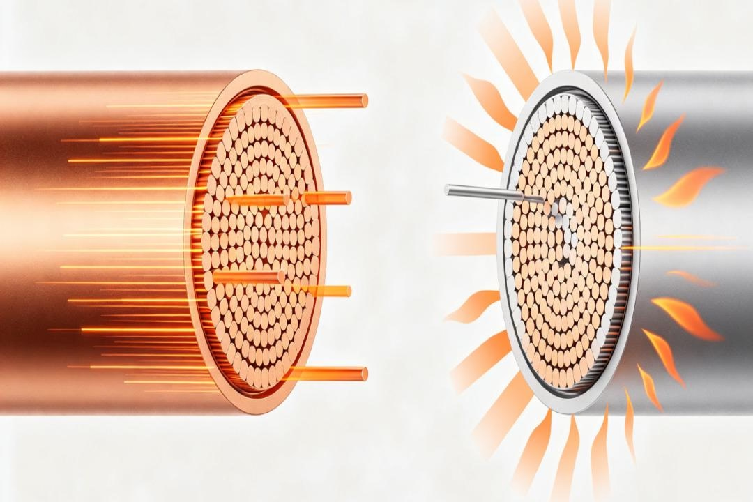
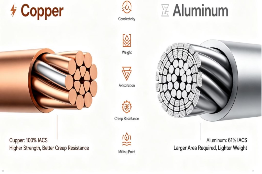
3D Technical Cutaway Comparison Of Copper And Aluminum Conductors. Copper Features Superior Conductivity With Efficient Current Flow And Less Heat Output. Aluminum Exhibits Higher Electrical Resistance, Leading To Greater Resistive Heat Dissipation For The Same Current Load.
Copper’s resistivity at 20°C is 1.724×10⁻⁸ Ω·m, while aluminum’s is 2.826×10⁻⁸ Ω·m. This means aluminum has roughly 64% higher resistance than copper for the same conductor size. To achieve the same performance, an aluminum conductor must be approximately 56% larger.
This is why copper remains the preferred choice for critical applications where space is limited, voltage drop must be minimized, and long-term reliability is essential.
Step 1: Understand the Core Formula
The foundation of every copper cable resistance calculator is a simple physics equation:
R = ρ × L / A
Where:
R = Resistance in ohms (Ω)
ρ (rho) = Resistivity of the conductor material (Ω·m)
L = Length of the conductor in meters (m)
A = Cross-sectional area in square meters (m²)
For copper at 20°C, the resistivity (ρ) is 1.724×10⁻⁸ Ω·m.
This formula tells you the resistance of a single conductor. For a complete circuit, remember that current must travel out and back—so the total resistance is twice the one-way resistance.
The Practical Shortcut
Here is a handy shortcut that works well for copper cable:
Resistance per kilometre (Ω/km) = 19 ÷ Cross-sectional area (mm²)
For example:
A 2.5 mm² copper cable: 19 ÷ 2.5 = 7.6 Ω/km
A 4 mm² copper cable: 19 ÷ 4 = 4.75 Ω/km
A 10 mm² copper cable: 19 ÷ 10 = 1.9 Ω/km
For resistance per metre, simply divide by 1,000.
This shortcut is not exact—it is a rough approximation—but it is remarkably useful for quick estimates in the field.
Step 2: Know Your Copper Cable’s Resistance Per Kilometre
For accurate calculations, you need precise resistance values. IEC 60228 and NEC standards provide these values for standard conductor sizes.
Metric Sizes (mm²) – DC Resistance at 20°C
| Conductor Size (mm²) | Plain Copper (Ω/km) | Tinned Copper (Ω/km) |
|---|---|---|
| 0.5 mm² | 36.0 | 36.7 |
| 0.75 mm² | 24.5 | 24.8 |
| 1.0 mm² | 18.1 | 18.2 |
| 1.5 mm² | 12.1 | 12.2 |
| 2.5 mm² | 7.41 | 7.56 |
| 4 mm² | 4.61 | 4.70 |
| 6 mm² | 3.08 | 3.11 |
| 10 mm² | 1.83 | 1.84 |
| 16 mm² | 1.15 | 1.16 |
| 25 mm² | 0.727 | 0.734 |
| 35 mm² | 0.524 | 0.529 |
| 50 mm² | 0.387 | 0.391 |
| 70 mm² | 0.268 | 0.270 |
| 95 mm² | 0.193 | 0.195 |
| 120 mm² | 0.153 | 0.154 |
| 150 mm² | 0.124 | 0.126 |
| 185 mm² | 0.0791 | 0.100 |
| 240 mm² | 0.0754 | 0.0762 |
| 300 mm² | 0.0601 | 0.0607 |
| 400 mm² | 0.0470 | 0.0475 |
Source: IEC 60228 conductor resistance standards
AWG Sizes – DC Resistance at 20°C
| AWG Size | Diameter (mm) | Area (mm²) | Plain Copper (Ω/km) |
|---|---|---|---|
| 30 AWG | 0.255 | 0.051 | 361 |
| 28 AWG | 0.321 | 0.081 | 227 |
| 26 AWG | 0.405 | 0.129 | 143 |
| 24 AWG | 0.511 | 0.205 | 89.4 |
| 22 AWG | 0.644 | 0.326 | 56.4 |
| 20 AWG | 0.812 | 0.518 | 35.3 |
| 18 AWG | 1.024 | 0.823 | 22.1 |
| 16 AWG | 1.291 | 1.31 | 13.9 |
| 14 AWG | 1.628 | 2.08 | 8.68 |
| 12 AWG | 2.052 | 3.31 | 5.42 |
| 10 AWG | 2.588 | 5.26 | 3.41 |
| 8 AWG | 3.264 | 8.37 | 2.14 |
| 6 AWG | 4.115 | 13.3 | 1.34 |
| 4 AWG | 5.189 | 21.2 | 0.84 |
| 2 AWG | 6.544 | 33.6 | 0.53 |
| 1/0 AWG | 8.251 | 53.5 | 0.33 |
| 2/0 AWG | 9.266 | 67.4 | 0.26 |
| 3/0 AWG | 10.40 | 85.0 | 0.21 |
| 4/0 AWG | 11.68 | 107.2 | 0.16 |
Sources: NEC Chapter 9 Table 8, ASTM B258
Step 3: Account for Temperature—Because Copper Gets Hotter
Here is a fact that catches many people off guard: Copper cable resistance changes with temperature.
At 20°C, copper has a resistivity of 1.724×10⁻⁸ Ω·m. But cables rarely operate at 20°C. In a conduit on a hot day, or carrying heavy current, conductor temperatures can reach 75°C, 90°C, or even higher.
The temperature coefficient of resistance for copper is 0.00393 per degree Celsius. This means that for every 1°C increase in temperature, the resistance increases by 0.393%.
The Temperature Correction Formula
R₂ = R₁ × [1 + α × (T₂ – T₁)]
Where:
R₁ = Resistance at the reference temperature (T₁)
R₂ = Resistance at the target temperature (T₂)
α (alpha) = Temperature coefficient of resistance for copper (0.00393 /°C)
T₁ = Reference temperature in °C (typically 20°C)
T₂ = Target temperature in °C
Real-World Example
A 100-foot length of 12 AWG copper wire has a resistance of approximately 0.1588 ohms at 20°C. If the conductor warms to 75°C (a typical operating temperature for fully loaded cable), the resistance becomes:
R₂ = 0.1588 × [1 + 0.00393 × (75 – 20)]
R₂ = 0.1588 × [1 + 0.00393 × 55]
R₂ = 0.1588 × [1 + 0.21615]
R₂ = 0.1588 × 1.21615
R₂ = 0.1931 ohms
That is a 21.6% increase in resistance. At 90°C, the increase is even greater—approximately 27.5%.
Why This Matters
NEC Chapter 9, Table 8 provides conductor resistance values at 75°C, not 20°C. This is because conductors in real installations operate at elevated temperatures. If you use 20°C resistance values for a 75°C installation, you will underestimate the actual resistance and voltage drop.
Always correct for temperature when performing voltage drop calculations for real-world installations.
Step 4: Use a Copper Cable Resistance Calculator—The Smart Way
You can do the math by hand, but why would you? Online calculators and mobile apps make the process fast, accurate, and error-free.
What a Good Calculator Should Do
A proper copper cable resistance calculator should allow you to:
Select copper or aluminum as the conductor material
Enter conductor length (one-way)
Input cross-sectional area in mm² or AWG
Specify the operating temperature (or use 20°C as default)
Account for parallel conductors (if applicable)
Return the DC resistance in ohms
Support IEC 60228 and NEC Table 8 standards
Example Calculation Using an Online Tool
Scenario: You are designing a 150-metre, 80-amp DC circuit at 600V. The maximum allowable voltage drop is 3% (18V). You are considering 2 AWG copper.
Using a resistance calculator:
| Parameter | Value |
|---|---|
| Material | Copper |
| Size | 2 AWG (33.6 mm²) |
| Length | 150 m |
| Temperature | 20°C |
| Resistance | 0.077 Ω |
| Voltage Drop (80A) | 6.16V |
| Verdict | Pass (6.16V < 18V) |
For comparison, using 4 AWG copper (21.2 mm²) would give approximately 0.121 Ω and a voltage drop of 9.7V—still acceptable, but with less margin. Using 6 AWG (13.3 mm²) would push the voltage drop close to the limit.
Where to Find Calculators
Several free tools are available online:
Cirris Wire Resistance Calculator – Quick AWG-based resistance lookup
IEE Business Wire Resistance Calculator – Supports temperature correction and parallel conductors
OSGeo Cable Resistance Calculator – Supports both copper and aluminum, DC and AC
KW Cable Resistance Calculator – Input length, area, and temperature
Search Google for “copper cable resistance calculator” to find these and other tools.
Step 5: Apply the Results to Real-World Installations
Knowing the resistance is only half the battle. Here is how to use that information.
Voltage Drop Calculation
Once you know the resistance, calculating voltage drop is simple:
Voltage Drop = Current × Resistance
For a single-phase circuit, remember to use the total loop resistance (out and back):
V_drop = I × (2 × R_one-way)
Practical Voltage Drop Limits
The NEC recommends keeping voltage drop within:
3% for branch circuits
5% for combined feeder and branch circuits
If your calculated voltage drop exceeds these limits, you need a larger conductor.
Power Loss (I²R Losses)
Resistance also creates power loss:
Power Loss = I² × R
In a 100A circuit with 0.1Ω resistance, the power loss is 100² × 0.1 = 1,000W. Over a year of continuous operation, that is nearly 9,000 kWh of wasted energy.
Cable Sizing Decision Tree
Calculate the one-way resistance using the formula or calculator
Correct for temperature if operating above 20°C
Calculate voltage drop (using 2× one-way resistance for single-phase)
Compare voltage drop to the 3% or 5% limit
If too high → select a larger conductor and repeat
If acceptable → verify ampacity and termination temperature ratings
Common Mistakes to Avoid
Mistake 1: Forgetting the Return Path
Resistance values are typically given for a single conductor. In a circuit, current must travel out and back. Always use twice the one-way resistance for voltage drop calculations.
Mistake 2: Using 20°C Values for 75°C Installations
NEC Table 8 values are at 75°C. If you use 20°C values from other sources, you will underestimate resistance and voltage drop. Correct for temperature.
Mistake 3: Ignoring Temperature Coefficient
Copper resistance increases by 0.393% per °C. At 75°C, that is a 21.6% increase. This is not negligible—it can push a marginal design over the edge.
Mistake 4: Confusing AWG and mm²
AWG and mm² are not interchangeable. A 10 AWG conductor is 5.26 mm², not 10 mm². Always verify the correct cross-sectional area.
Mistake 5: Using Stranded Wire Nominal Area Without Correction
Stranded conductors can have 1–2% higher resistance than solid conductors of the same nominal area. For precision work, apply a stranding factor.
Frequently Asked Questions
Q: What is the resistance of copper cable per metre?
A: It depends on the cross-sectional area. For a 2.5 mm² copper cable, resistance is approximately 0.0076 Ω/m (7.6 Ω/km ÷ 1000). For a 10 mm² cable, it is approximately 0.0019 Ω/m.
Q: How do I calculate copper cable resistance from AWG?
A: Use the formula R = ρ × L / A, where A is the cross-sectional area of the AWG size. AWG to mm² conversion charts are widely available.
Q: What is the resistivity of copper?
A: At 20°C, the resistivity of copper is 1.724×10⁻⁸ Ω·m.
Q: How does temperature affect copper cable resistance?
A: Copper resistance increases by 0.393% per degree Celsius. At 75°C, resistance is about 21.6% higher than at 20°C.
Q: What is the difference between copper and aluminum resistance?
A: Aluminum has roughly 64% higher resistance than copper for the same conductor size. To achieve the same performance, an aluminum conductor must be approximately 56% larger.
Q: Where can I find official resistance values for copper cables?
A: Official values are published in IEC 60228 and NEC Chapter 9, Table 8. Search Google for “IEC 60228 conductor resistance” or “NEC Table 8 resistance” to find reference tables.
Conclusion
The copper cable resistance calculator is not just a tool—it is your insurance policy against voltage drop, overheating, and system failure. Every metre of cable adds resistance. Every amp of current creates voltage drop. Every degree of temperature increases resistance.
By mastering the five steps in this guide—understanding the formula, knowing your cable’s resistance per kilometre, accounting for temperature, using a calculator effectively, and applying the results to real-world installations—you can design electrical systems that work reliably, efficiently, and safely.
Stop guessing. Start calculating. Your equipment—and your clients—will thank you.
References
IEC 60228 – Conductors of insulated cables
NEC Chapter 9, Table 8 – Conductor Properties
IEEE 835 – Standard Power Cable Ampacity Tables
RS Online – How to calculate resistance of a copper cable
Cirris – Wire Resistance Calculator & Temperature Coefficient
IEE Business – Wire Resistance Calculator
Various engineering reference sites including elecalculator.com and kwcalc.com
This guide is for informational purposes only. Always consult the latest edition of the National Electrical Code and work with qualified professionals for electrical installations.