 Minxing Cable
 Jinhuanyu Cable
 Jinlongyu Cable
 Guangdong Cable
 Zhujiang Wire & Cable




Introduction
Every electrical engineer, contractor, and electrician has faced the same fundamental question: What size copper cable do I need for this circuit? The answer lies in understanding ampacity—the maximum current a conductor can carry continuously without exceeding its temperature rating.
The copper cable ampacity chart is not just a reference table; it is the foundation of safe electrical design. Selecting the wrong conductor size leads to overheated insulation, voltage drop, equipment failure, and potentially catastrophic fires. This guide provides a comprehensive look at copper cable ampacity, the National Electrical Code (NEC) Table 310.16, and the critical factors that determine how much current a copper cable can safely carry.
What Is Ampacity?
Ampacity, short for “ampere capacity,” is the maximum steady-state electrical current a conductor can carry under specified conditions without exceeding its rated temperature. As current flows through a conductor, it generates heat due to the conductor’s electrical resistance. If too much current passes through a cable, the heat buildup can damage the insulation, melt the conductor, or start a fire.
The ampacity of a copper cable depends on three primary factors:
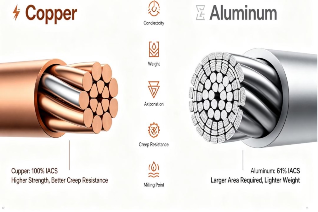
Conductor material – Copper has higher conductivity than aluminum, allowing smaller copper conductors to carry the same current.
Insulation type – Different insulation materials have different maximum temperature ratings.
Ambient temperature – Higher surrounding temperatures reduce a cable’s ability to dissipate heat.
The National Electrical Code (NEC), published by the National Fire Protection Association (NFPA) as NFPA 70, establishes the standard ampacity tables used throughout the United States.
NEC Table 310.16: The Standard Reference
The primary reference for copper cable ampacity is NEC Table 310.16 (formerly Table 310.15(B)(16)), titled Ampacities of Insulated Conductors with Not More Than Three Current-Carrying Conductors in Raceway, Cable, or Earth (Directly Buried).
This table applies to:
Conductors rated 0–2000 volts
Not more than three current-carrying conductors in a raceway or cable
Ambient temperature of 30°C (86°F)
The table provides ampacity values across three temperature columns, each corresponding to different insulation types:
| Temperature Rating | Insulation Types |
|---|---|
| 60°C (140°F) | TW, UF |
| 75°C (167°F) | RHW, THHW, THW, THWN, XHHW, XHWN, ZW |
| 90°C (194°F) | TBS, SA, SIS, FEP, FEPB, MI, PFA, RHH, RHW-2, THHN, THHW, THW-2, THWN-2, USE-2, XHH, XHHW, XHHW-2, XHWN, XHWN-2, XHHN, Z, ZW-2 |
Complete Copper Ampacity Chart (NEC Table 310.16)
The following table shows allowable ampacities for copper conductors based on NEC Table 310.16:
| Conductor Size (AWG/kcmil) | 60°C (140°F) | 75°C (167°F) | 90°C (194°F) |
|---|---|---|---|
| 18* | — | — | 14A |
| 16* | — | — | 18A |
| 14* | 15A | 20A | 25A |
| 12* | 20A | 25A | 30A |
| 10* | 30A | 35A | 40A |
| 8 | 40A | 50A | 55A |
| 6 | 55A | 65A | 75A |
| 4 | 70A | 85A | 95A |
| 3 | 85A | 100A | 115A |
| 2 | 95A | 115A | 130A |
| 1 | 110A | 130A | 145A |
| 1/0 | 125A | 150A | 170A |
| 2/0 | 145A | 175A | 195A |
| 3/0 | 165A | 200A | 225A |
| 4/0 | 195A | 230A | 260A |
| 250 kcmil | 215A | 255A | 290A |
| 300 kcmil | 240A | 285A | 320A |
| 350 kcmil | 260A | 310A | 350A |
| 400 kcmil | 280A | 335A | 380A |
| 500 kcmil | 320A | 380A | 430A |
| 600 kcmil | 350A | 420A | 475A |
| 700 kcmil | 385A | 460A | 520A |
| 750 kcmil | 400A | 475A | 535A |
| 800 kcmil | 410A | 490A | 555A |
| 900 kcmil | 435A | 520A | 585A |
| 1000 kcmil | 455A | 545A | 615A |
Note: Sizes marked with an asterisk (*) are subject to overcurrent protection limitations under NEC 240.4(D). Overcurrent protection shall not exceed 15 amperes for 14 AWG, 20 amperes for 12 AWG, and 30 amperes for 10 AWG copper after any correction factors for ambient temperature and number of conductors have been applied.
The Three Temperature Columns: What They Mean
60°C Column (140°F)
This column applies to older insulation types like TW (thermoplastic wet) and UF (underground feeder). These insulations have lower heat tolerance and are less common in modern installations. However, NEC 110.14(C) requires that for circuits 100 amps or less (or conductors 1 AWG and smaller), the 60°C column must be used unless all terminations are rated for 75°C.
75°C Column (167°F)
This is the most practical column for everyday electrical work. Most modern breakers, lugs, and equipment terminations are rated for 75°C. Common insulation types in this column include THWN, THW, XHHW, and USE. When you see a wire gauge ampacity chart for residential or commercial applications, the 75°C column is typically the one that governs real-world installations.
90°C Column (194°F)
THHN and XHHW-2 are among the most common 90°C-rated insulations. However, you almost never get to use the 90°C column for final ampacity because terminations (breakers, lugs, connectors) are typically rated at 75°C. The 90°C column serves a critical purpose: it is the starting point for derating calculations. When applying ambient temperature corrections or adjustment factors for more than three conductors, you begin with the 90°C ampacity—the final value just cannot exceed the 75°C column limit.
Factors That Affect Copper Cable Ampacity

Key Variables Impacting Cable Ampacity: Ambient Temperature, Bundled Conductor Quantity, Insulation Class And Installation Method.
The values in the ampacity chart assume ideal conditions: 30°C ambient temperature and no more than three current-carrying conductors. In the real world, these conditions are rarely met. You must apply correction factors and adjustment factors to determine the true ampacity of a copper cable in your specific installation.
1. Ambient Temperature Correction
NEC Table 310.15(B)(1) provides correction factors for ambient temperatures other than 30°C (86°F). As ambient temperature rises, a cable’s ability to dissipate heat decreases, reducing its ampacity.
For example, a rooftop conduit in direct sunlight can experience ambient temperatures of 45–55°C. At 50°C ambient, the correction factor for a 90°C-rated conductor is approximately 0.82. A 10 AWG copper conductor rated at 40A in the 90°C column would be derated to 40 × 0.82 = 32.8A.
2. Conductor Count Adjustment (Raceway Fill)
When more than three current-carrying conductors are bundled in a raceway, cable, or tray, heat dissipation is reduced. NEC Table 310.15(C)(1) requires adjustment factors:
| Number of Current-Carrying Conductors | Adjustment Factor |
|---|---|
| 1–3 | 1.00 |
| 4–6 | 0.80 |
| 7–9 | 0.70 |
| 10–20 | 0.50 |
| 21–30 | 0.45 |
| 31–40 | 0.40 |
| 41 and above | 0.35 |
For example, a 6 AWG copper conductor rated at 75A in the 90°C column (or 65A in the 75°C column) with six current-carrying conductors in a conduit would require derating to 75 × 0.80 = 60A (starting from 90°C column), but the final ampacity cannot exceed the 75°C column value of 65A.
3. Insulation Type
Different insulation materials have different maximum operating temperatures, as shown in the three columns of Table 310.16. Using a 90°C-rated insulation like THHN provides more headroom for derating than a 60°C-rated insulation like TW.
4. Installation Method
Whether conductors are installed in raceway, cable, direct burial, or free air affects ampacity. Table 310.17 provides ampacities for single insulated conductors in free air, which are generally higher than those in raceway due to better heat dissipation.
The Termination Temperature Rule: What Most People Miss
Perhaps the most misunderstood aspect of copper cable ampacity is the termination temperature rule under NEC 110.14(C) . This rule states that the ampacity of a conductor cannot exceed the lowest temperature rating of any termination in the circuit.
Practical implications:
For circuits 100A or less (or 1 AWG and smaller): Use the 60°C column unless every termination (breaker, lug, connector) is listed and marked for 75°C. Most modern breakers are 75°C-rated, which is why many electricians use the 75°C column in practice.
For circuits over 100A: Equipment is assumed to be 75°C-rated, so the 75°C column applies.
The 90°C column is for derating math only. You can start with the 90°C ampacity when applying temperature correction and conductor count adjustment factors, but the final ampacity cannot exceed the 75°C column value.
Worked Examples: Applying the Ampacity Chart
Example 1: Residential Branch Circuit
Scenario: You need to install a 20A branch circuit for receptacles in a residential kitchen. The cable will run through a wall with three other current-carrying conductors in the same raceway. Ambient temperature is 30°C (86°F).
Step 1: Determine the base ampacity from Table 310.16. A 12 AWG copper conductor has an ampacity of 25A in the 75°C column and 30A in the 90°C column.
Step 2: Check the termination temperature rule. For a 20A circuit (≤100A), use the 60°C column unless terminations are 75°C-rated. With modern 75°C breakers, we can use the 75°C column: 12 AWG = 25A.
Step 3: Apply conductor count adjustment. With 4–6 conductors, the adjustment factor is 0.80. Starting from the 90°C column (30A × 0.80 = 24A), the final ampacity cannot exceed the 75°C column value (25A). So the adjusted ampacity is 24A.
Step 4: The circuit requires a 20A overcurrent protection device. 24A ≥ 20A → the 12 AWG conductor is acceptable.
Example 2: Commercial Feeder
Scenario: A 100A subpanel is fed by a copper conductor in a conduit with an ambient temperature of 45°C (113°F). There are three current-carrying conductors total.
Step 1: Base ampacity from Table 310.16. For a 100A circuit, 3 AWG copper at 75°C is rated 100A.
Step 2: Ambient temperature correction. At 45°C, the correction factor for 75°C-rated conductors is approximately 0.87. 100A × 0.87 = 87A.
Step 3: The derated ampacity (87A) is less than the required 100A load. A larger conductor is needed. 2 AWG at 75°C is rated 115A. 115A × 0.87 = 100.05A → 2 AWG is the minimum acceptable size.
Example 3: Derating with Multiple Conductors
Scenario: Eight 10 AWG THHN copper conductors are installed in a single conduit. Ambient temperature is 30°C.
Step 1: Base ampacity from 90°C column: 10 AWG = 40A.
Step 2: Conductor count adjustment for 7–9 conductors: factor = 0.70.
Step 3: Adjusted ampacity = 40A × 0.70 = 28A.
Step 4: Check termination temperature rule. 10 AWG at 75°C is rated 35A. The final ampacity (28A) does not exceed the 75°C column value (35A), so 28A is the allowable ampacity.
Step 5: Per NEC 240.4(D), overcurrent protection for 10 AWG copper cannot exceed 30A. The adjusted ampacity is 28A, so a 25A or 30A breaker would be appropriate.
Common Mistakes When Using the Ampacity Chart
Mistake 1: Using the 90°C Column for Final Ampacity
Many electricians see “THHN” on the wire and immediately use the 90°C column. This is incorrect. NEC 110.14(C) requires that terminations limit the ampacity. Unless the entire circuit—including breakers, lugs, and connectors—is rated for 90°C, you cannot use the 90°C column for final sizing.
Mistake 2: Ignoring Ambient Temperature
A cable rated for 30A at 30°C cannot carry 30A at 45°C. Ambient temperature correction is not optional—it is required by code. Failing to apply correction factors leads to overheated conductors and insulation failure.
Mistake 3: Overlooking Conductor Count Adjustment
When more than three current-carrying conductors are bundled, heat cannot dissipate effectively. The adjustment factors in NEC Table 310.15(C)(1) must be applied. Many installers forget this step, especially in crowded panels and conduits.
Mistake 4: Confusing Ampacity with Overcurrent Protection
A conductor’s ampacity is the maximum current it can carry. The overcurrent protection device (breaker or fuse) must protect the conductor at or below this ampacity. For small conductors (14 AWG, 12 AWG, 10 AWG), NEC 240.4(D) caps overcurrent protection at 15A, 20A, and 30A respectively, even if the conductor’s ampacity is higher.
Copper vs. Aluminum: Why Copper Matters
Copper is the preferred conductor material for most applications because of its superior properties:
| Property | Copper | Aluminum |
|---|---|---|
| Conductivity (% IACS) | 100% | ~61% |
| Tensile Strength | Higher | Lower |
| Corrosion Resistance | Excellent | Moderate |
| Thermal Expansion | Lower | Higher |
| Creep Resistance | Superior | Inferior |
Copper’s higher conductivity means that for the same ampacity, a copper conductor can be smaller than an aluminum one, saving space in conduits and panels. Its superior tensile strength and creep resistance also make terminations more reliable over the long term.
Practical Guidelines for Copper Cable Selection
For Residential Applications
| Circuit Amperage | Minimum Copper Size (60°C/75°C) | Common Use |
|---|---|---|
| 15A | 14 AWG | Lighting, general outlets |
| 20A | 12 AWG | Kitchen receptacles, small appliances |
| 30A | 10 AWG | Clothes dryers, water heaters, A/C units |
| 40A | 8 AWG | Ranges, large A/C units |
| 50A | 6 AWG | Subpanels, EV chargers |
| 100A | 3 AWG (75°C) / 2 AWG (60°C) | Main service panels |
For Commercial and Industrial Applications
For larger loads, always consult the full NEC Table 310.16. A few reference points:
| Circuit Amperage | Minimum Copper Size (75°C) |
|---|---|
| 125A | 1/0 AWG |
| 150A | 2/0 AWG |
| 200A | 4/0 AWG or 250 kcmil |
| 225A | 250 kcmil |
| 300A | 350 kcmil |
Frequently Asked Questions
Q: What is the ampacity of 12 AWG copper wire?
A: According to NEC Table 310.16, 12 AWG copper is rated at 20A (60°C), 25A (75°C), or 30A (90°C). However, per NEC 240.4(D), overcurrent protection for 12 AWG is limited to 20A.
Q: Can I use the 90°C column for THHN wire?
A: Only for derating calculations. The final ampacity is limited by the termination temperature rating, typically 75°C for most equipment. Use the 75°C column for final sizing.
Q: How does ambient temperature affect ampacity?
A: Higher ambient temperatures reduce ampacity. NEC Table 310.15(B)(1) provides correction factors. For example, at 40°C ambient, a 90°C-rated conductor is derated to approximately 0.91 of its 30°C value.
Q: What happens if I exceed a cable’s ampacity?
A: Exceeding ampacity causes excessive heat buildup, which can damage insulation, create voltage drop, and potentially start a fire. Always size conductors to handle the continuous load plus 125% for continuous loads per NEC requirements.
Q: Where can I find the official NEC ampacity tables?
A: The official tables are published in NFPA 70, the National Electrical Code. They are also available through various online references and the NFPA website. Google’s search results provide numerous resources, including tables from engineering reference sites and electrical supply companies.
Conclusion
The copper cable ampacity chart—specifically NEC Table 310.16—is an indispensable tool for anyone involved in electrical design, installation, or maintenance. Understanding how to read and apply this table is not just a matter of code compliance; it is a matter of safety.
Remember these key takeaways:
Ampacity is the maximum current a conductor can carry without exceeding its temperature rating.
NEC Table 310.16 provides base ampacities for copper conductors under standard conditions (30°C ambient, ≤3 conductors).
Three temperature columns (60°C, 75°C, 90°C) correspond to different insulation types.
Termination temperature rules (NEC 110.14(C)) often limit you to the 75°C column for final sizing.
Correction factors for ambient temperature and conductor count must be applied in real-world installations.
Small conductor rules (NEC 240.4(D)) cap overcurrent protection for 14 AWG, 12 AWG, and 10 AWG.
By mastering these principles, you can select the right copper cable for every application—ensuring safety, code compliance, and long-term reliability. When in doubt, always consult the latest edition of the National Electrical Code and seek guidance from qualified professionals.
References
National Electrical Code (NFPA 70), Table 310.16 – Ampacities of Insulated Conductors
NEC Table 310.15(B)(1) – Ambient Temperature Correction Factors
NEC Table 310.15(C)(1) – Adjustment Factors for More Than Three Current-Carrying Conductors
NEC 110.14(C) – Temperature Limitations of Terminations
NEC 240.4(D) – Small Conductor Overcurrent Protection
Various engineering reference sites including engineersedge.com, kristechwire.com, and elecalculator.com
This guide is for informational purposes only. Always consult the latest edition of the National Electrical Code and work with qualified professionals for electrical installations.